
Today’s modern lift equation used in the calculation of the aerodynamic forces is based on Newton’s third law and evolution of the lift equation established by Sir George Cayley in England. In this section, we look at two of the most supported explanations, including Newton’s third law of action and reaction and Bernoulli’s equation for the conservation of energy. There are numerous theories and a number of associated controversies of how lift is generated. In reality, drag and lift are transmitted at every point on the surface of the object and therefore can be thought of in terms of net forces rather than single-point sources. Drag is applied in the opposite direction to motion. It is a mechanical force generated by the difference in velocity between the object and fluid. In addition to the lift, objects that move through a fluid are subjected to aerodynamic friction, called drag force. In both cases, the object is subjected to a lift force, perpendicular to the flow. In contrary to the aircraft, where the object (i.e., aircraft) moves through the fluid (i.e., atmospheric air), the gas turbine’s compressed air moves through the object (i.e., blades). As applies to the gas turbine blades, the fluid is the air stream passing through the gas turbine. Lift is defined by NASA as a mechanical force generated by a solid object moving through a fluid. Lift, the same mechanism responsible for flying an aircraft, is also responsible for the gas turbine blade rotation. Hiyam Farhat, in Operation, Maintenance, and Repair of Land-Based Gas Turbines, 2021 Introduction to basic principles of lift The layout of the morphing rib was properly adapted to fit the geometry of the flap device at each spanwise section defined in Fig. On the other hand, actuator A1 is powered off during morphing mode 2. During morphing mode 1, the secondary leverage is fixed because only actuator A1 is activated. The secondary leverage amplifies the torque of the actuator and makes B4 to rotate around hinge C, thus implementing the tab-like morphing. The position of the link L and of the pivots of the leverage M1 are selected in a way that, upon the rotation of A1 shaft, all the rib blocks rotate around hinges A, B, C according to specific angles compliant with the external morphed shapes to be achieved.Ī secondary leverage (M2) links B4 to B3 and is driven by the rotation of the actuator A2. At the same time, blocks B1 and B3 are forced to follow the movement being mutually interconnected to the remaining blocks. The rotation induced by A1 makes M1 to move, and therefore changes the relative position of block B2 with respect to block B4.

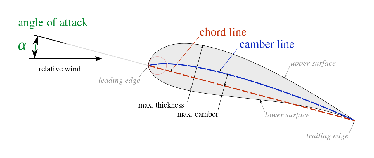
Blocks B1 and B3 are interconnected by means of a suitably shaped beam (L) having two hinges at the edges internal leverage (M1) connects blocks B2 and B4 and is activated by the external rotary actuator (A1). Structural design considers both operational loads (dive velocity, V d) and aeroelastic limits.īlocks are allowed to rotate with respect to each other, thus making the airfoil camber line to morph. Management of the digital mock-up (DMU) is crucial in individuating possible interferences and other manufacture and integration issues. The structural concept has been finalized after an iterative design process consisting of three main loops the executive layout has been obtained by progressive updates of a sketched configuration, on the basis of feasibility assessment and stress analyses outcomes. It is relevant to remark that, per the previous statements and particularly the fact that the structural system is a “mechanism,” the motors have the unique role to guarantee a certain shape is reached and held. (B) Indication of the hinges connecting the structural blocks (A, B, and C in the order) and defining the attachment of the mechanical links to the structural blocks (D and E for L1 F and G for L2). (A) Indication of the structural blocks (B0, B1, B2, and B3) and the mechanical links (L1 and L2).


 0 kommentar(er)
